Introduction to I2C and the LCD Display
Objective
The objective of this lab is a learn the basics of an example that uses the I2C bus to control the LCD Display.
In this lab, you will change the LCD background color to Intel Blue and display the text “Intel Blue”
Disable the Program Writing the IP Address to the LCD
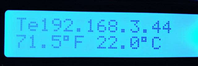
When you boot the Up2 Board, there is a system service that launches at boot that will display your IP address on an LCD. This program is running in the background and you need to disable it before you can use the LCD in a lab.
 Open a terminal and SSH to the Up2 Board
ssh upsquared@<your ip address>
Run this command to stop the ip_addr_c service.
systemctl stop ip_addr_c
Now you can process with labs that make use of the LCD screen.
Identifying When You Are Running Multiple Processes Using I2C
It’s often problematic to run more that one program that makes use of I2C simultaneously. Here are two way that you can know if this is happening:
-
Text on the LCD display is garbled, or text is overwriting previously displayed text in a confusing manner.

-
I2C bus errors. Sometimes multiple processes writing to the I2C bus will cause the I2C bus subsystem to crash. If you are seeing an I2C error then rebooting the Up2 will often fix the problem.
Hardware requirements
| Module | Pin |
|---|---|
| LCD Display | Any I2C Port |
 Connect LCD Display to Any I2C Port.
I2C using the Arduino API
Create a new project
#include <stdio.h>
#include <jhd1313m1.h>

#include "upm_utilities.h"

int main(void)
{
    // Char array to hold LCD message
    char str[20];

    // Initialize the subplatform
    mraa_add_subplatform(MRAA_GROVEPI, "0");

    // Initialize the LCD context
    jhd1313m1_context lcd = jhd1313m1_init(0, 0x3e, 0x62);

    // Handle Initialization errors
    if (!lcd)
    {
        printf("jhd1313m1_i2c_init() failed\n");
        return 1;
    }

    while (1)
    {
      // Set str to "Intel Blue"
      snprintf(str, sizeof(str), "Intel Blue");

      // Set the display cursor to the upper left
      jhd1313m1_set_cursor(lcd, 0, 0);

      // Write the string to the LCD
      jhd1313m1_write(lcd, str, strlen(str));

      // Set color to Intel Blue
      uint8_t r = 0;
      uint8_t g = 113;
      uint8_t b = 197;

      // Set the LCD back light color
      jhd1313m1_set_color(lcd, r, g, b);

      // Debugging output to the serial monitor
      printf("rgb: 0x%02x%02x%02x\n", r, g, b);

      upm_delay(1);
    }

    // Close the LCD context
    jhd1313m1_close(lcd);

    return 0;
}
Viewing the Serial Monitor
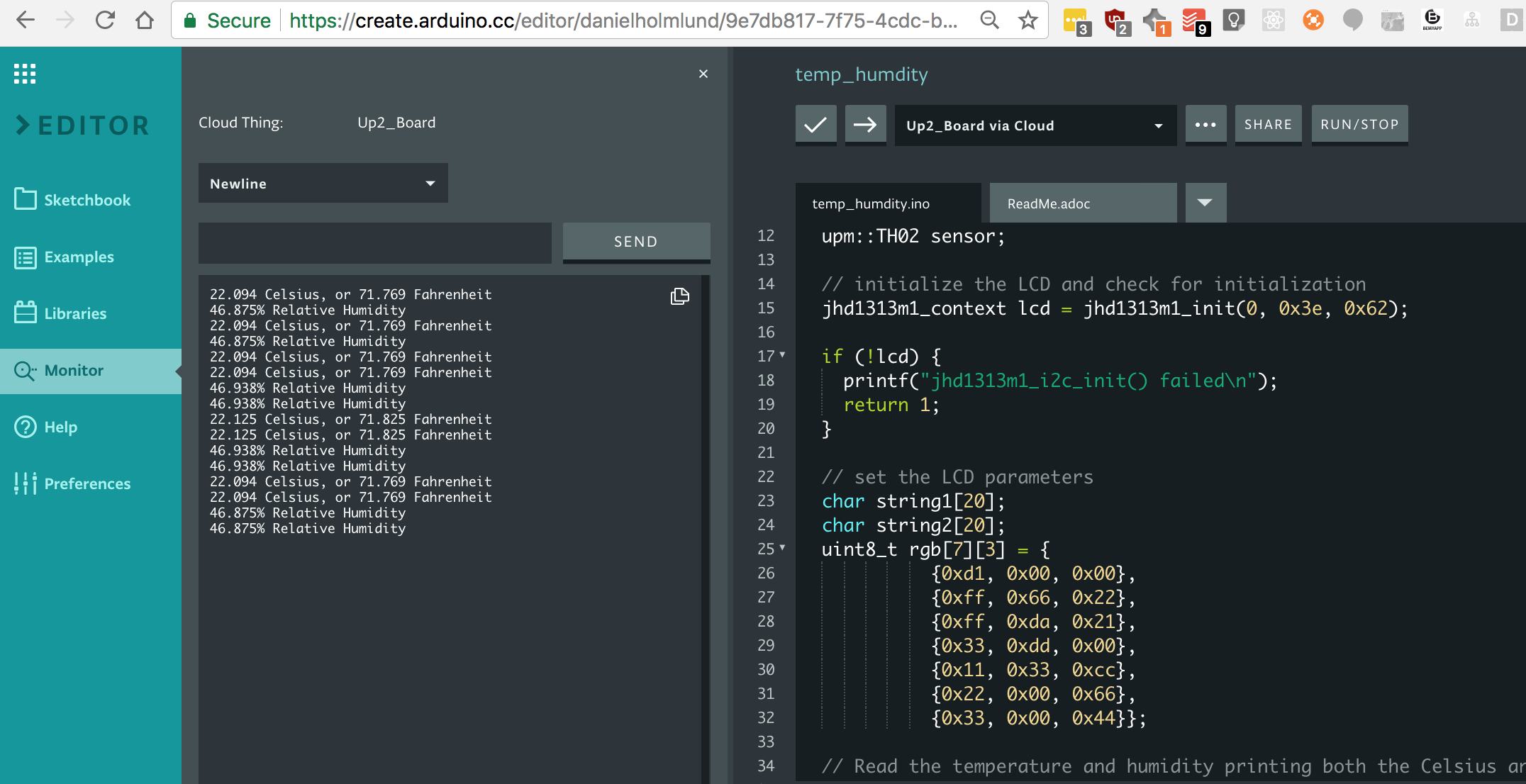
Be sure to use the serial monitor to debug your programs. It can be found in the left side bar.

Additional resources
Information, community forums, articles, tutorials and more can be found at the Intel Developer Zone.
For reference code for any sensor/actuator from the Grove* IoT Commercial Developer Kit, visit https://software.intel.com/en-us/iot/hardware/sensors